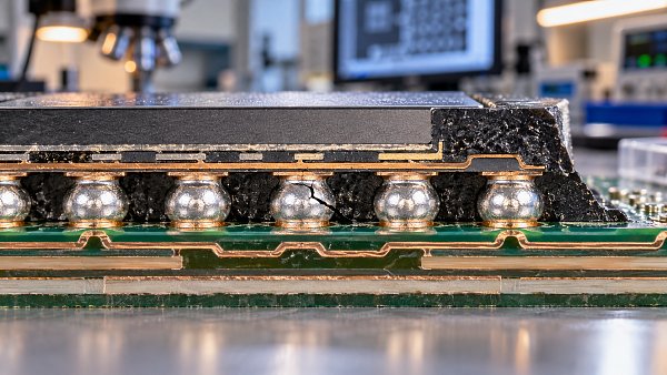
What causes solder joint failure in ball grid array packages?
Author
Date Published
Reading Time
Solder joint failure in Ball Grid Array Packages can compromise electrical connections, product reliability, and safety in demanding applications. Common causes include thermal cycling, mechanical stress, manufacturing defects, and material or process incompatibilities, but the actual failure mechanism depends on operating conditions and package design. For quality control and safety teams, understanding these risks is essential to setting inspection criteria, investigating failures, and preventing recurrence.
The difficult part is that a failed joint may have passed production testing. A weak connection can remain electrically functional until repeated temperature changes, board bending, or vibration turn a small defect into an intermittent open circuit. A useful investigation therefore asks two separate questions: what created the vulnerable joint, and what load caused it to fail?
Why BGA solder joints are vulnerable
A ball grid array connects a package to a printed circuit board through an array of solder joints underneath the component. These connections carry electrical signals and power, while also forming part of the mechanical attachment. Their position makes direct visual inspection difficult once the package is assembled.
The package and board do not necessarily expand and contract by the same amount. As temperatures change, that mismatch imposes repeated deformation on the solder. Joint geometry, package size, substrate construction, board thickness, and the position of each ball all influence the resulting stress. Outer joints can be particularly exposed to relative movement, although the actual failure location depends on the assembly.
Mechanical loading adds another dimension. A board that flexes during connector insertion or enclosure assembly may stress a joint in a way that is unrelated to its normal operating temperature. In practice, thermal and mechanical loads can combine with a manufacturing defect, making it misleading to assign every cracked joint to a single cause.
Thermal cycling and solder fatigue
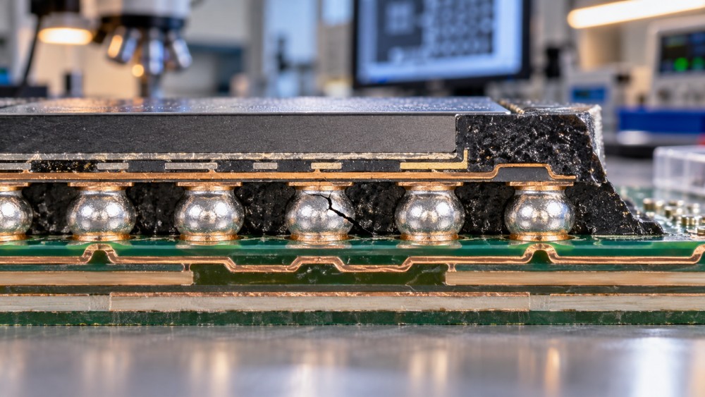
Thermal fatigue is a common concern when equipment repeatedly heats and cools during use. The solder deforms as the package and board move relative to each other. Over many cycles, damage can accumulate and a crack may develop through the solder or near an interface. An intermittent connection can appear before the circuit becomes permanently open.
The relevant temperature history is the one experienced by the assembly, not merely the ambient specification on a product sheet. Local component heating, power cycling, enclosure airflow, and neighboring devices can change the range and rate of temperature variation. A design used continuously in a controlled cabinet may experience a different fatigue profile from the same board used in equipment that starts and stops frequently.
For qualification, accelerated thermal cycling can help compare designs or process conditions, but it should not automatically be treated as a field-life prediction. Temperature extremes, dwell times, ramp rates, sample size, and the definition of failure all matter. A result is most useful when the test conditions are documented and linked to the intended application.
Board flex, shock, and vibration
A solder joint may crack because the board bends during depanelization, handling, installation, or service. Pressing a connector into place near a large BGA, tightening an enclosure unevenly, or applying force during rework can create localized strain. The component may show no obvious external damage, and the failure can be intermittent when the board returns to its original shape.
Shock and vibration introduce different loading patterns. The risk depends on how the board is mounted, its natural response, the component’s mass and location, and the duration and direction of the load. A stiffener or revised mounting arrangement may reduce movement in one area, but it can also redirect stress elsewhere. Any design change needs assembly-level verification rather than an assumption that more stiffness always solves the problem.
For quality teams, the practical question is when the strain occurs. Review handling fixtures, support locations, connector forces, depanelization methods, and service procedures alongside field conditions. If failures cluster around a particular assembly operation, monitoring board strain during that operation may be more informative than repeating a generic vibration test.
Reflow defects and hidden assembly weaknesses
Some BGA failures begin before the product leaves the factory. Insufficient or inconsistent solder paste, contamination, oxidation, placement variation, and unsuitable reflow conditions can prevent a joint from forming as intended. The issue may affect a single ball, a region of the package, or an entire production lot.
A reflow profile must be assessed at the assembly, not just at the oven setting. Board mass, component distribution, package construction, and loading affect the temperatures actually reached. Too little effective heating can contribute to poor wetting or incomplete coalescence; excessive thermal exposure can damage materials or alter interfaces. Use the applicable paste, package, and board supplier guidance to establish a compatible process window.
Package or board warpage during heating can also change the contact between solder deposits and balls. One possible outcome is a head-in-pillow defect, in which the ball and paste do not fully join even though they are close together. Such a joint may make electrical contact initially and fail later under load. Conversely, excessive solder or alignment problems can contribute to bridging between adjacent connections.
Voids deserve careful interpretation. Their presence alone does not establish that a joint will fail. Size, location, joint function, applicable acceptance criteria, and the observed failure mechanism all matter. Treating every visible void as the root cause can distract from a crack, non-wet interface, or handling problem that is more relevant to the failure.
Materials, interfaces, and process changes
A BGA joint is a system of materials: the solder ball, paste, package-side and board-side finishes, copper features, and surrounding substrate all interact. Intermetallic compounds form at solder interfaces as part of normal bonding. Their characteristics can change with processing and time at temperature; under some conditions, an interface may become more susceptible to brittle fracture.
Changing solder alloy, surface finish, flux chemistry, or package supplier can therefore alter more than purchase cost. A replacement may be acceptable in isolation but behave differently with the existing board finish or thermal profile. Moisture-sensitive packages also require storage, handling, and reflow controls consistent with the supplier’s instructions; uncontrolled moisture exposure can damage the package during heating.
Supplier localization is not, by itself, evidence of equivalence. When a material or package source changes, compare specifications and traceability, then qualify the complete assembly under representative conditions. Ask what has been demonstrated in a laboratory, what has been qualified for the intended application, and what is supported by sustained production records.
How to investigate an intermittent BGA failure
Begin by preserving evidence. Record the affected product, serial and lot information, failure symptoms, operating history, and any previous repair. If safety-related functions are involved, contain potentially affected units according to the organization’s risk and escalation procedures before destructive analysis begins.
Try to reproduce the failure without changing the assembly unnecessarily. Electrical testing at relevant temperatures or under controlled mechanical loading may reveal an intermittent connection, but avoid aggressive probing or bending that could create additional damage. Compare failed units with unaffected units from the same and different lots where available.
Inspection methods answer different questions:
- X-ray inspection can reveal solder distribution, bridging, and some voids or assembly anomalies beneath the package. A conventional image may not reliably resolve every fine crack or distinguish every weak interface.
- Electrical continuity testing confirms behavior at the test conditions, but a passing result does not rule out an intermittent joint that opens only under temperature or strain.
- Cross-sectioning and microscopy can expose joint geometry, cracks, and interfaces. They are destructive, and the section must intersect the relevant feature; preparation artifacts also need consideration.
- Fracture-surface and materials analysis may help distinguish fatigue, brittle interface fracture, and assembly-related non-wetting when used with the electrical and process history.
Do not reflow or remove the suspect package before deciding what evidence is needed. Rework can change the microstructure and obscure the original fracture. A sound conclusion connects the observed damage to a plausible load and to records such as paste inspection, reflow profiles, board handling, supplier changes, and field exposure.
Turning findings into production controls
Corrective action should target the mechanism, not just the failed part. If cross-sections show non-wetting and records indicate unstable paste deposition, replacing the BGA does not control the process. Investigate stencil condition, printing, storage, surface cleanliness, and the actual reflow profile. If the fracture is consistent with board flex, examine fixtures and assembly forces before changing the solder alloy.
Set inspection and acceptance criteria against the product’s requirements and the applicable revision of agreed standards. IPC-A-610 is commonly used for electronic assembly acceptability, while J-STD-001 addresses requirements for soldered electrical and electronic assemblies. Their application depends on the contract, product class, and agreed criteria; neither replaces a product-specific reliability assessment.
For a safety-relevant design, also examine what happens when the connection fails. An open on a redundant signal may have a different consequence from an intermittent power or control connection. Failure-mode analysis, diagnostics, system-level fault response, and applicable regulatory requirements should inform the control plan. A solder joint that passes visual or X-ray acceptance is not automatically proof that the system is safe.
When reviewing suppliers or alternative processes, request the conditions behind reliability claims: package and board construction, solder materials, test profile, sample size, failure definition, and whether the results represent qualification or ongoing production. FabBrief, a proposed semiconductor manufacturing information portal, approaches packaging decisions with that distinction in mind. For the next production review, keep the same discipline: identify the expected load, verify the assembly process, and make sure the evidence supports the actual product configuration.
Questions about market trends? Contact Market Scope Live for deeper business insights.
We respect your privacy. Your information is strictly confidential.
We respect your privacy. Your information is strictly confidential.
Related News
 Yield ImprovementWhen can photomask defect inspection miss printable defects?Photomask defect inspection can miss printable defects. Discover key causes, review triggers, and practical ways to strengthen mask quality and wafer yield.MORE+
 Yield ImprovementWhat causes solder joint failure in ball grid array packages?Ball Grid Array Packages can fail due to thermal cycling, board flex, and hidden assembly defects. Discover how to investigate failures and improve reliability.MORE+
 Yield ImprovementWhy Is Wafer Chipping Increasing During Dicing?Why is wafer chipping increasing during dicing? Explore blade, cooling, mounting and process factors, and discover practical steps to protect yield.MORE+
 Yield ImprovementWhat affects photoresist coating uniformity across a wafer?Photoresist Coaters and Developers: Discover what affects wafer coating uniformity and how to troubleshoot thickness variation for a more stable lithography process.MORE+
 Yield ImprovementHow temperature uniformity affects diffusion furnace yieldSemiconductor Diffusion Furnaces depend on temperature uniformity for consistent yields. Explore how to diagnose variations and evaluate furnace performance.MORE+
 Yield ImprovementWhat causes poor contact in semiconductor probe stations?Semiconductor Probe Stations can suffer poor contact due to dirty tips, misalignment, or electrical faults. Discover practical ways to isolate and resolve the cause.MORE+