Can a Die Bonder Handle Warped Wafers?
Author
Date Published
Reading Time
A die bonder can handle warped wafers when its complete handling and bonding sequence accommodates the wafer’s measured shape without unacceptable damage, placement error, or yield loss. Compare the wafer’s deformation with the supplier’s limits first, but make sure both measurements describe the same wafer condition, support method, and process stage. Then verify the result with representative wafers on the intended tool configuration.
A single maximum warp value is rarely enough. A wafer that loads successfully can still fail to sit flat on a chuck, move during die pickup, or produce inconsistent bond-line thickness. The relevant limit is the one demonstrated across the steps the product actually requires.
Start with the wafer as it reaches the bonder
Measure the wafer at the point in the process where it will enter the equipment. Grinding, deposition, temporary bonding, dicing, and removal from a carrier can change its shape. A value recorded before thinning, for example, does not establish the deformation that the bonder will encounter after thinning and mounting on tape.
Record the wafer diameter, thickness, material stack, surface condition, and temperature at measurement. Include the mounting arrangement: a bare wafer, a wafer on dicing tape in a frame, and a wafer attached to a carrier present different mechanical conditions. If a film or adhesive is used, its type, tension, and process history can affect the shape presented to the tool.
Describe the geometry as well as the magnitude. A smooth bowl-shaped wafer, a saddle-shaped wafer, and a wafer with a sharply lifted edge can have similar reported values but behave differently at loading and clamping. A local edge lift may interfere with a gripper even when the center of the wafer is readily held down. A map or profile is more informative than a single number when explaining the problem to an equipment supplier.
Are bow and warp interchangeable?
No. Bow describes a departure of the wafer’s center relative to a reference surface under a defined measurement method. Warp generally describes the range of deviations across the wafer relative to a reference surface. Exact definitions, sign conventions, reference surfaces, and exclusion zones depend on the method used, so the labels alone do not guarantee a valid comparison.
Ask for the supplier’s measurement definition and compare it with the metrology report. Confirm whether the stated value refers to a free-standing wafer, a wafer supported at specified points, or a wafer held against a chuck. Gravity and support position can alter a thin wafer’s shape. A measurement with vacuum applied describes the clamped condition, not necessarily the deformation the loading mechanism must accept.
Also establish whether a limit is expressed as a signed bow, a total range, or a displacement at a particular location. A numerical comparison is misleading if one figure represents center deflection and the other represents a peak-to-valley range. Where the methods cannot be reconciled, arrange a measurement under agreed conditions or send representative samples for a handling trial.
Which part of the process sets the real limit?
Request separate limits for loading, alignment, chucking, die pickup, bonding, and unloading where those stages apply. A machine’s published wafer-handling range may describe its loader rather than its ability to maintain bond accuracy on the same wafer. The installed grippers, chuck, ejector, vision system, and process recipe all matter.
Loading and edge clearance
A warped wafer can tilt or catch during transfer from a cassette or frame. The relevant clearance depends on wafer orientation, edge position, and the path through the mechanism. A tool that accepts one curvature direction may need a different setup for the opposite direction. Verify that sensors detect the wafer reliably and that the transfer does not scrape the edge or active surface.
Chucking and flattening
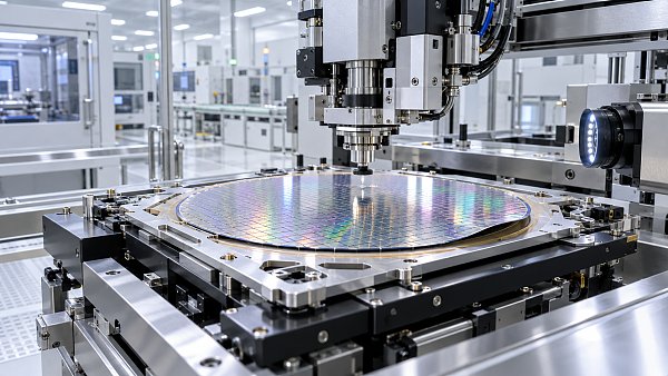
A vacuum chuck may pull a compliant wafer closer to flat, but it must maintain contact without exceeding the wafer’s mechanical limits. Excessive force or an unsuitable support pattern can crack a thin wafer, damage a film, or create localized distortion. Conversely, incomplete contact can leave areas elevated, reduce positional stability, or affect temperature uniformity during a heated process.
Ask how the tool detects loss of vacuum and whether its chuck design supports the wafer, frame, or carrier in the proposed configuration. A successful clamp should be assessed by the resulting position and process outcome, not simply by the presence of a vacuum signal. If heating is involved, confirm performance at bonding temperature and after thermal stabilization; a room-temperature shape does not necessarily represent the process condition.
Die pickup versus wafer bonding
For die bonding from a diced wafer, the relevant path includes the wafer frame, tape, ejector, pickup tool, and die-release behavior. Curvature can change the local height seen by the pickup system or alter how tape responds to ejection. Confirm that the system can locate and pick die across the usable wafer area, including regions with the greatest height variation, without causing die damage or missed picks.
For a process that bonds a whole wafer, the concerns shift toward surface conformity, alignment, contact initiation, and the resulting interface. A tool intended for individual die placement should not be assumed to support wafer-to-wafer bonding merely because it can load a warped wafer. Define the actual bonding process before comparing specifications.
What should a supplier specification state?
A useful specification ties its limit to a named configuration and a defined outcome. A statement such as “handles warped wafers” leaves open whether the wafer can be transferred, flattened, aligned, or processed at the required quality. Request the following context for any quoted limit:
- Measurement basis: bow or warp definition, measurement tool or method, reference surface, support arrangement, and units.
- Wafer condition: diameter, thickness, material stack, curvature profile, and whether the wafer is bare, taped, framed, or carrier-supported.
- Equipment setup: loader, chuck, gripper, pickup or bonding head, sensors, and relevant software or recipe options.
- Process conditions: temperature, vacuum, cycle sequence, and any restrictions on curvature direction or local edge lift.
- Demonstrated result: the operation completed and the criteria used to judge handling, placement, bond quality, and damage.
Distinguish a standard configuration from an option, a custom modification, or an experimental setup. If a special chuck or carrier is required, establish whether it is included in the proposed configuration and whether it is compatible with upstream and downstream handling. A limit demonstrated on a thicker wafer or a different film stack is evidence to investigate, not proof of equivalence.
Run an acceptance test that exposes the difficult cases
Agree on the test protocol before shipment or installation, including sample selection, measurement method, operating conditions, pass criteria, and responsibility for evaluation. Include wafers that represent the range expected at the bonder, especially the most challenging shapes that remain within the intended incoming specification. Select samples from actual process conditions where possible; a mechanically bent substitute may not reproduce the stiffness, local profile, or surface properties of a processed wafer.
Measure and identify each test wafer before processing. Record its orientation, profile, mounting condition, and any visible defects. Run the intended sequence, including automatic loading and unloading if those are part of production. Manual placement can be useful for diagnosis, but it does not demonstrate that the automated transfer path will work.
The test should capture the point at which a problem occurs. A transfer alarm, a vacuum fault, a failed alignment, and a bond defect require different remedies. Preserve equipment logs and inspect the wafer or die after relevant steps so that a final reject is not attributed to the wrong mechanism.
Define acceptance around product requirements rather than a generic demonstration. Depending on the process, evidence can include transfer completion, absence of new cracks or edge damage, die pickup performance, placement accuracy, and inspection of the bonded interface. For a process with adhesive, bond-line uniformity or void inspection may be relevant; for another bond type, the agreed interface assessment will differ. Specify the measurement locations and inspection methods before reviewing results.
Cycle time should be measured with the same handling steps and inspection assumptions intended for production. A recipe that achieves acceptable bonding only after repeated retries or a prolonged flattening step may be technically feasible while falling short of the required operating rate. Report retries, alarms, and rejected units alongside elapsed time rather than counting only completed cycles.
How much testing is enough?
One successful wafer demonstrates that one sample passed under one set of conditions. It does not establish the failure rate across incoming variation or sustained operation. The test scope should reflect the consequences of failure, available samples, and the variation in wafer shape, thickness, film stack, and orientation. State the number of wafers and die evaluated, the number of runs, and the acceptance criteria when recording the result.
Where production volume or sample availability prevents a conclusive trial, document the remaining uncertainty. A staged acceptance can separate initial tool functionality from later process qualification, provided both stages have agreed conditions and remedies. For example, the first stage might establish automated transfer and chucking; a later stage can evaluate bonding and yield on representative lots. Passing the first stage should not be described as qualification of the complete process.
When the wafer exceeds the stated limit
First determine whether the limit applies to the observed shape and the installed configuration. If it does, do not assume that stronger vacuum or slower handling will solve the problem. Flattening changes mechanical stress, and a wafer that appears stable on the chuck may spring back during release or transfer.
Possible changes include a different chuck or gripper, carrier-supported handling, adjustments to the upstream film stack, or a revised mounting and transfer sequence. Each change needs its own evaluation. A carrier can improve support while introducing adhesive, cleaning, alignment, or release requirements; modifying an upstream process can reduce curvature but also change product properties.
Keep the measured incoming-wafer range, the qualified equipment configuration, and the accepted process window together in the operating record. When wafer construction or the handling recipe changes, reassess whether the original trial still represents the condition reaching the bonder.
Questions about market trends? Contact Market Scope Live for deeper business insights.
We respect your privacy. Your information is strictly confidential.
We respect your privacy. Your information is strictly confidential.
Related News
 Advanced PackagingHow accurate do die bonders need to be for flip-chip assembly?Die Bonders for flip-chip assembly must meet post-bond alignment targets. Explore accuracy budgets, process factors and practical tips for choosing the right machine.MORE+
 Advanced PackagingWhen does system-in-package make sense for compact devices?System-in-Package can unlock space and performance in compact devices. Explore the thermal, cost, yield, and supply trade-offs before choosing SiP.MORE+
 Advanced PackagingHow to choose wire bonding equipment for fine-pitch devicesChoose Wire Bonding Equipment for fine-pitch devices with confidence. Compare placement accuracy, bond quality, throughput, supplier trials and ownership costs.MORE+
 Advanced PackagingWhy does ABF substrate warpage matter during chip assembly?ABF Substrates can warp during chip assembly, putting yield and reliability at risk. Discover how to measure deformation and control defects.MORE+
 Advanced PackagingHow Much Floor Space Does a Wire Bonding Machine Need?How much floor space does a wire bonding machine need? Explore footprint, access, utilities, and layout planning to make a confident equipment decision.MORE+
 Advanced PackagingCan a Die Bonder Handle Warped Wafers?How do I check whether a die bonder can handle warped wafers? Compare measurement methods, review process limits, and verify performance with representative wafers.MORE+
 Advanced PackagingWhen do semiconductor packaging substrates need finer line widths?When do Semiconductor Packaging Substrates need finer lines? Explore routing bottlenecks, electrical trade-offs, and supplier checks to make a confident design decision.MORE+
 Advanced PackagingHow underfill materials reduce thermal fatigue in flip-chip packagesDiscover how Semiconductor Underfill Materials reduce flip-chip thermal fatigue, and learn what to consider when selecting and qualifying a formulation.MORE+