How to choose wire bonding equipment for fine-pitch devices
Author
Date Published
Reading Time
Choose wire bonding equipment for fine-pitch devices by qualifying it on the actual package, wire, pad geometry and production conditions—not by accepting a minimum-pitch figure or headline bond rate alone. The preferred system should place bonds within the available clearance, produce acceptable interconnections throughout the intended operating window, and sustain that performance with the required inspection and service arrangements.
The distinction matters when a machine bonds a demonstration coupon successfully but struggles with a real device: pad edges may be close to passivation, neighboring loops may encroach on one another, or the package may distort during heating. A technically credible comparison therefore starts with the complete bonding application and ends with evidence from representative lots, defined acceptance tests and an operating-cost model.
Define the bonding task before comparing machines
Prepare an application package for each supplier. Include drawings of the die and substrate, pad dimensions and center-to-center pitch, passivation openings, metallization and top-surface condition. Identify bond locations, wire count, loop heights, spans, neighboring features and any keep-out areas. State whether the device is a single die, stacked die or another assembly, and describe the carrier or strip format presented to the machine.
Pitch alone is not the usable bonding area. A small pad opening, variation in die position or an oversized ball can leave much less placement margin than the pitch suggests. Ask suppliers to show the relationship between the finished bond footprint and the permitted bond area, including manufacturing tolerances. For second bonds, check the available landing area and clearance from adjacent traces or package features separately.
Also identify the intended wire material and diameter, bonding surface materials, thermal limits, upstream cleaning or plasma treatment, and downstream encapsulation. Surface oxidation, contamination and substrate finish can change the process window; a machine evaluated on a substitute surface may not demonstrate readiness for the actual assembly.
Match the bonding method to the materials and geometry
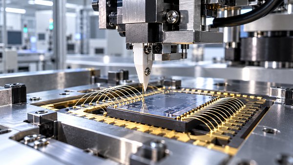
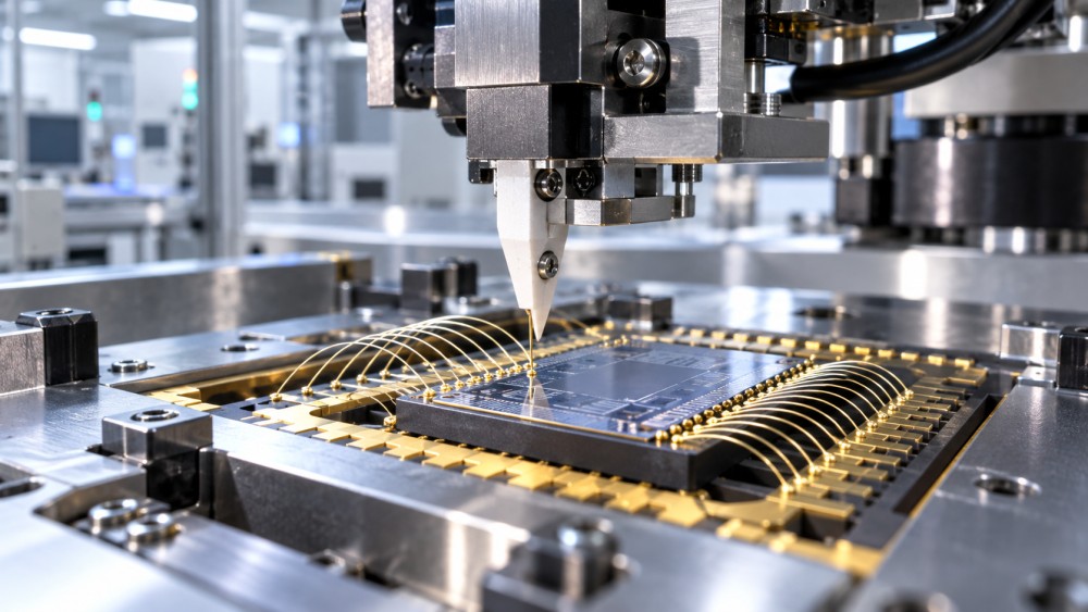
Fine-pitch work often calls for thermosonic ball bonding, but the correct method depends on the assembly. Ball bonding forms a free-air ball and generally uses heat, ultrasonic energy and force to make the first bond. Wedge bonding uses a different tool geometry and is used with suitable wires and bond surfaces; it can be appropriate where access or material choices favor it. Neither method should be selected from pitch alone.
Confirm that the proposed configuration supports the specified wire, capillary or wedge, bond surfaces, stage temperature and loop geometry. Gold, copper, coated copper and aluminum wires have different process and handling requirements. For copper ball bonding, for example, ask how the system controls the protective atmosphere during free-air ball formation and how that control is monitored. Compatibility should be demonstrated with the actual wire and metallization, not inferred from a general equipment brochure.
Review access to the bond sites as well. Stacked dies, recessed areas and tall adjacent components can restrict tool approach and loop formation. A supplier should identify any tooling changes, motion constraints or package-orientation restrictions needed to reach every site, including the most difficult first and second bonds.
Turn placement specifications into a usable tolerance budget
A published accuracy or repeatability figure is useful only when its definition and test conditions are clear. Ask whether it describes machine motion, vision alignment, measured bond placement or another characteristic; whether it applies to both axes; and whether it is reported as a maximum, a statistical value or a different measure. Check the measurement method, temperature, calibration state and time period. Unlike a completed bond-placement result, a stage specification may exclude errors from imaging, package movement and bond formation.
Build a tolerance budget around the actual allowable bond area. Consider die and substrate position variation, fiducial location, vision recognition, stage motion, thermal expansion, workholder stability and bond footprint variation. These contributions cannot automatically be added or combined without understanding their distributions and correlations. The practical test is whether measured bond locations and footprints remain within drawing limits across representative positions and operating conditions, with margin for normal variation.
Inspect the vision system’s ability to find features on the real surface. Reflective metal, low-contrast passivation, changing lighting and contamination can affect recognition. Evaluate alignment at the corners as well as the center of the work area, and ask how the machine handles rejected images, missing fiducials and changes in strip or die orientation. An operator intervention requirement may be acceptable for a pilot line but materially affect automated production.
Qualify bond quality, not just successful placement
Placement within the opening is necessary but does not establish an acceptable interconnection. Agree on bond shape and footprint limits, loop clearance, tail condition, wire sweep susceptibility and other relevant visual criteria for the package. Check for bond lift, cratering or damage to underlying structures using methods appropriate to the device and its reliability requirements.
Define the electrical, mechanical and reliability evidence needed for the application before the trial. Depending on the materials and customer requirements, this may include wire pull, ball shear, cross-section analysis, electrical continuity and post-stress inspection. Specify sample locations, sample size, test conditions and pass criteria in advance. Destructive test results should be interpreted with failure mode and test method, not just a single force value.
Ask the supplier to demonstrate a process window rather than a single optimized recipe. Evaluate relevant combinations of bond force, ultrasonic energy, time and temperature within safe limits, then examine how results change with expected variation in surfaces, wire and equipment settings. The aim is not to maximize one test reading at the expense of pad damage or another failure mode; it is to establish a repeatable region that satisfies the complete set of criteria.
For sensitive pad structures or low-strength dielectrics, include the device owner’s damage-screening requirements early. A bond that passes an initial pull test can still be unsuitable if the underlying structure is damaged. Likewise, a clean appearance immediately after bonding does not replace the reliability testing required for the intended service environment.
Compare throughput using the same workload
Request cycle-time estimates and measurements for the same bond map, package handling sequence, wire type and inspection settings. State the number of bonds, loop lengths, alignment operations and any required changes between products. A machine’s advertised bonds per hour may exclude loading, vision retries, index moves, operator interventions or quality checks.
For planning, separate the measured bonding cycle from net output over a defined shift or production period. Include expected changeovers, scheduled cleaning, consumable replacement, calibration, maintenance and realistic stoppages. Record which allowances are estimates and replace them with site data as it becomes available. Yield must use the same unit and boundary in each comparison: a wire-level defect rate, a package-level yield and a final test yield are not interchangeable.
Automation can alter the result. An integrated handler, automatic wire threading or process monitoring may reduce labor and interruptions, but only if it works with the site’s carriers, traceability system and product mix. During evaluation, include recovery from a broken wire, a rejected image and an interrupted strip. Note whether recovery preserves lot identity and whether partially processed units require manual review.
Plan a representative supplier trial
A useful trial is an agreed experiment, not an open-ended demonstration. Provide representative material from normal upstream processes where possible, including relevant variation in pad condition and package dimensions. Identify the hardest bond locations and include the full bond map if throughput or loop interaction is part of the decision. Record any substitute material or special preparation that could limit the result’s transfer to production.
- Set the comparison conditions. Give each supplier the same drawings, materials, bond count and acceptance criteria. Document proposed tooling, consumables and any differences in setup.
- Establish a baseline recipe. Record machine configuration, software version, wire lot, surface preparation and process settings. Allow for normal setup and optimization, but keep those activities visible.
- Measure across the work area. Assess placement, bond quality and loop clearance at defined positions, including difficult sites and locations away from the primary alignment reference.
- Test repeatability over time. Where material and schedule permit, repeat runs after routine interruptions or consumable changes. Record adjustments, rejected units and operator actions rather than reporting only the best run.
- Close the evidence gaps. Complete agreed mechanical, electrical and reliability evaluations. Distinguish results obtained in the supplier’s laboratory from those reproduced on the receiving line.
A trial may establish technical feasibility without proving production readiness. Qualification on the actual line still needs to address installation, utilities, upstream variation, operator training and the site’s inspection and release procedures. Agree who owns each remaining task and what evidence will be required before a purchase decision or production release.
Examine support and ownership costs before committing
Compare quotations on a common scope. A low base price may omit the heater, workholder, vision options, handler interface, process monitoring, tooling or acceptance support required for the fine-pitch application. Identify recurring consumables, including wire, capillaries or wedges, clamps and other wear parts, along with expected maintenance intervals and the assumptions behind them.
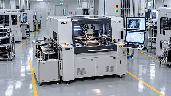
Review electrical, gas, exhaust, temperature and facility requirements against the proposed configuration. Confirm footprint and access for loading and maintenance, integration with manufacturing execution and traceability systems, data formats, user permissions and software support. For every critical spare, ask about local availability, replenishment lead time and the supplier’s service response arrangements; contractual terms matter more than an informal assurance.
The purchase acceptance plan should distinguish factory acceptance from site acceptance. Define the material, bond map, test methods, throughput calculation, measurement equipment and remedies for missed criteria. Include training and documentation, and specify how recipe changes, software updates and calibration records will be controlled after installation. A machine that passes a narrow factory demonstration but lacks an agreed path to site qualification leaves the most consequential risk with the buyer.
Questions about market trends? Contact Market Scope Live for deeper business insights.
We respect your privacy. Your information is strictly confidential.
We respect your privacy. Your information is strictly confidential.
Related News
 Advanced PackagingHow accurate do die bonders need to be for flip-chip assembly?Die Bonders for flip-chip assembly must meet post-bond alignment targets. Explore accuracy budgets, process factors and practical tips for choosing the right machine.MORE+
 Advanced PackagingWhen does system-in-package make sense for compact devices?System-in-Package can unlock space and performance in compact devices. Explore the thermal, cost, yield, and supply trade-offs before choosing SiP.MORE+
 Advanced PackagingHow to choose wire bonding equipment for fine-pitch devicesChoose Wire Bonding Equipment for fine-pitch devices with confidence. Compare placement accuracy, bond quality, throughput, supplier trials and ownership costs.MORE+
 Advanced PackagingWhy does ABF substrate warpage matter during chip assembly?ABF Substrates can warp during chip assembly, putting yield and reliability at risk. Discover how to measure deformation and control defects.MORE+
 Advanced PackagingHow Much Floor Space Does a Wire Bonding Machine Need?How much floor space does a wire bonding machine need? Explore footprint, access, utilities, and layout planning to make a confident equipment decision.MORE+
 Advanced PackagingCan a Die Bonder Handle Warped Wafers?How do I check whether a die bonder can handle warped wafers? Compare measurement methods, review process limits, and verify performance with representative wafers.MORE+
 Advanced PackagingWhen do semiconductor packaging substrates need finer line widths?When do Semiconductor Packaging Substrates need finer lines? Explore routing bottlenecks, electrical trade-offs, and supplier checks to make a confident design decision.MORE+
 Advanced PackagingHow underfill materials reduce thermal fatigue in flip-chip packagesDiscover how Semiconductor Underfill Materials reduce flip-chip thermal fatigue, and learn what to consider when selecting and qualifying a formulation.MORE+