How Much Floor Space Does a Wire Bonding Machine Need?
Author
Date Published
Reading Time
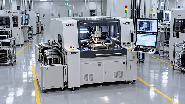
How much floor space does a wire bonding machine need? The answer depends on more than the machine’s stated footprint. Equipment dimensions, operator access, maintenance clearance, material handling, and utility connections all shape the usable space required. For packaging engineers and procurement teams, these factors can influence tool placement, production flow, and installation costs. This guide explains how to assess the footprint and surrounding requirements, helping you plan a layout that fits both the equipment and its operating conditions.
There is no reliable universal floor-area figure for a wire bonder. A manual bench-top machine, a stand-alone automatic bonder, and an automated system with loading and unloading equipment have different spatial demands. Start with the dimensions of the exact configuration, then add the areas needed to operate, maintain, supply, and move materials around it. Those surrounding areas can matter as much to the layout as the machine itself.
The footprint is only the starting point
A published footprint usually describes the space occupied by the machine under a defined configuration. It may not include an operator’s chair, an open access panel, a separate controller, an external chiller, a material cart, or the clearance needed to replace components. Dimensions can also change when a feeder, magazine handler, conveyor, or other option is added.
Before using a specification sheet in a building plan, establish what its dimensions represent. Ask whether width and depth include protruding handles, cable connections, utility fittings, and any parts that extend beyond the base. For a bench-top bonder, include the bench, its load capacity, and the operator’s working position rather than treating the machine’s base as the entire installation.
The useful distinction is between equipment footprint and allocated production area. The first describes the tool. The second describes the space the factory must protect for that tool to function without obstructing people, neighboring equipment, or required access.
How to build a workable space estimate
Use a scaled layout rather than adding a single percentage to a catalog footprint. Begin with the supplier’s installation drawing for the intended configuration. Draw the machine, associated cabinets, and fixed utility equipment, then map the spaces that must remain available during operation and maintenance.
The following are separate questions, even when some of their areas can overlap:
- Operation: Where does the operator stand or sit, load material, inspect the process, and respond to alarms?
- Maintenance: Which panels open, which components are removed, and from which side does a technician need access?
- Material flow: Where do incoming and outgoing magazines, trays, leadframes, or other carriers wait?
- Utilities: Where do power, air, vacuum, gas, network, or cooling connections enter, if required by the configuration?
- Movement and safety: Can people, carts, and service equipment pass without blocking access or required routes?
Do not automatically add every clearance rectangle together: an aisle may serve several machines, and a maintenance space may be shared if the site can control its use. Equally, do not assume all clearances can overlap. A maintenance operation that requires simultaneous access to two adjacent machines, for example, may expose a constraint that a simple area calculation misses. Confirm shared-space assumptions with the equipment supplier and the site’s facilities and safety teams.
A simple illustration shows why the distinction matters. Suppose an imagined machine body is 1.0 m wide by 1.2 m deep, giving a 1.2 m² equipment footprint. If the approved arrangement, including the access zones that must remain clear, fits within a 2.2 m by 2.4 m rectangle, the allocated rectangle is 5.28 m². These numbers are arithmetic examples, not recommended dimensions or typical machine specifications. Actual clearances and the final boundary must come from the selected tool and site requirements.
The calculation also needs a clear boundary. If the 2.2 m by 2.4 m rectangle includes part of a shared aisle, decide whether that aisle is charged to the individual machine or to the production area as a whole. Either accounting method can be useful; mixing them makes equipment comparisons misleading.
Where space requirements change by machine type
A manual or semi-automatic bonder may look compact on paper, but its working area is shaped by the person using it. A bench, microscope or viewing system, seating, lighting, and space for handling parts can determine the actual station size. Operator posture and reach deserve attention: squeezing the bench into an available corner is not a good layout if loading or inspection becomes awkward.
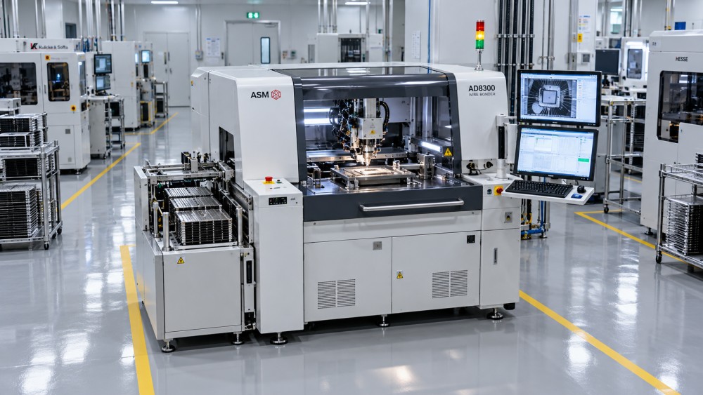
An automatic wire bonder shifts more of the space question toward equipment access and material presentation. Its loading arrangement may use magazines, trays, or a specific carrier format. The machine may require space for replenishment even when no operator remains at the tool continuously. Check the actual loading direction and whether material can be transferred without crossing a service zone or a neighboring machine’s access area.
Inline automation adds another boundary problem. A bonder integrated with conveyors or adjacent process equipment should be assessed as part of a line, not as an isolated rectangle. Transfer heights, handoff positions, bypass arrangements, and recovery from a stopped machine can affect spacing. A compact tool is less useful if its orientation creates a bottleneck at the interface.
Bonding method alone is not a dependable shortcut for estimating area. Ball and wedge bonding systems can differ in handling, process options, and supporting equipment, but the relevant layout is the one supplied for the particular model and configuration.
Access space is not wasted space
Maintenance clearance is often the first area to disappear when a floor plan becomes crowded. That decision can be expensive later. Technicians may need to open covers, replace wire or tooling, reach electrical components, inspect a handling mechanism, or remove a module. The required access depends on the machine design and on which tasks the factory expects to perform locally.
Ask the supplier to identify both routine and major-service access. A panel that opens for inspection may need less room than a component that must be pulled out horizontally. Also check whether service access requires temporary lifting equipment, a cart, or an unobstructed path to an exit. A drawing showing doors open is more useful than a single clearance number without context.
Shared service space can work, provided the factory has a practical way to keep it clear. A marked zone that becomes permanent storage is not a maintenance plan. Where two machines share access, consider whether planned maintenance schedules, emergency repairs, and neighboring production can coexist without moving equipment or interrupting a line.
Utilities, environmental conditions, and the installation route
A tool can fit geometrically and still be difficult to install. Confirm utility types and connection locations for the chosen configuration. Depending on the machine, these may include electrical power, compressed air, vacuum, process gas, network connectivity, or cooling. Do not assume every wire bonder needs all of them. Check service capacity, connection points, hose and cable routing, isolation requirements, and whether supporting equipment is included in the supplier’s footprint.
Routing matters because a connection at the rear of a machine can compete with a wall, a service corridor, or another tool. Hoses and cables also need to be protected from traffic and positioned so they do not prevent access. If a separate cabinet or chiller is required, locate it on the drawing and check its own ventilation and service needs.
The equipment supplier should also provide applicable environmental and floor requirements, including machine weight, load distribution, leveling, and any sensitivity to vibration or temperature. Cleanliness expectations depend on the product and process; the fact that a machine is used in semiconductor packaging does not by itself establish the site’s required cleanroom classification.
Finally, trace the delivery route from receiving to the installation point. Door openings, lifts, floor loading, turning space, packaging dimensions, and rigging arrangements can all constrain the move. The shipping envelope may differ from the operating footprint, and the route needed for a future replacement may be harder to protect once the production area is full.
Compare capacity, not just square meters
A smaller machine is not automatically the better use of floor space. The relevant comparison is the area needed to produce the required qualified output under the intended product mix. Machine cycle time, wire count, loading, changeovers, inspection, maintenance, and yield can all affect the number of tools and support stations needed.
A supplier’s maximum throughput figure is useful for understanding a machine’s capability, but it should not be treated as sustained factory output without its conditions. Ask what product, bond pattern, handling configuration, and operating assumptions support the stated figure. Then evaluate the layout against the factory’s own expected utilization and qualification needs. A plan based on optimistic output may leave no room for the additional equipment needed to meet demand.
This is also where expansion planning becomes practical. Reserving space for another bonder is not enough if the future machine cannot share utilities, access, or material flow without disrupting the first. Conversely, committing a large area to an unconfirmed expansion can constrain current operations. Mark future capacity separately from installed capacity and revisit it as the production plan becomes firmer.
What to request before approving the layout
For each candidate machine, request the installation drawing and utility requirements for the exact quoted configuration, including options and any external equipment. Ask the supplier to identify operating, maintenance, and component-removal clearances; shipping dimensions and weight; and the assumptions behind material loading and unloading. Where specifications are still provisional, record which dimensions can change before order release.
Review those documents with manufacturing engineering, facilities, maintenance, and the people responsible for material handling. The goal is not merely to show that the machine fits, but to identify who owns each adjacent space and whether it remains available during real work. Local building, electrical, fire, and workplace requirements should be checked with the appropriate site specialists rather than inferred from a generic equipment brochure.
FabBrief’s proposed coverage of semiconductor manufacturing and procurement emphasizes this distinction between a published specification and the conditions required for deployment. For a wire bonder, the decision-ready figure is the allocated area supported by a reviewed layout—not an isolated width multiplied by depth. Before finalizing the floor plan, obtain the configuration-specific drawings, settle any shared-clearance assumptions, and verify the installation route.
Questions about market trends? Contact Market Scope Live for deeper business insights.
We respect your privacy. Your information is strictly confidential.
We respect your privacy. Your information is strictly confidential.
Related News
 Advanced PackagingHow accurate do die bonders need to be for flip-chip assembly?Die Bonders for flip-chip assembly must meet post-bond alignment targets. Explore accuracy budgets, process factors and practical tips for choosing the right machine.MORE+
 Advanced PackagingWhen does system-in-package make sense for compact devices?System-in-Package can unlock space and performance in compact devices. Explore the thermal, cost, yield, and supply trade-offs before choosing SiP.MORE+
 Advanced PackagingHow to choose wire bonding equipment for fine-pitch devicesChoose Wire Bonding Equipment for fine-pitch devices with confidence. Compare placement accuracy, bond quality, throughput, supplier trials and ownership costs.MORE+
 Advanced PackagingWhy does ABF substrate warpage matter during chip assembly?ABF Substrates can warp during chip assembly, putting yield and reliability at risk. Discover how to measure deformation and control defects.MORE+
 Advanced PackagingHow Much Floor Space Does a Wire Bonding Machine Need?How much floor space does a wire bonding machine need? Explore footprint, access, utilities, and layout planning to make a confident equipment decision.MORE+
 Advanced PackagingCan a Die Bonder Handle Warped Wafers?How do I check whether a die bonder can handle warped wafers? Compare measurement methods, review process limits, and verify performance with representative wafers.MORE+
 Advanced PackagingWhen do semiconductor packaging substrates need finer line widths?When do Semiconductor Packaging Substrates need finer lines? Explore routing bottlenecks, electrical trade-offs, and supplier checks to make a confident design decision.MORE+
 Advanced PackagingHow underfill materials reduce thermal fatigue in flip-chip packagesDiscover how Semiconductor Underfill Materials reduce flip-chip thermal fatigue, and learn what to consider when selecting and qualifying a formulation.MORE+