Does a PVD Tool Need a Dedicated Cooling Water Supply?
Author
Date Published
Reading Time
Does a PVD tool need a dedicated cooling water supply? Not necessarily: the answer depends on the tool’s heat load, cooling-water specifications, facility infrastructure, and the manufacturer’s installation requirements.
A shared plant system may be suitable when it meets the required flow, temperature, pressure, and water-quality limits, while some configurations may need a dedicated chiller or isolated cooling loop.
Understanding these conditions early can help engineering and procurement teams assess installation costs, process stability, and utility risks before selecting a physical vapor deposition system.
When Is a Shared Cooling Water Supply Enough?
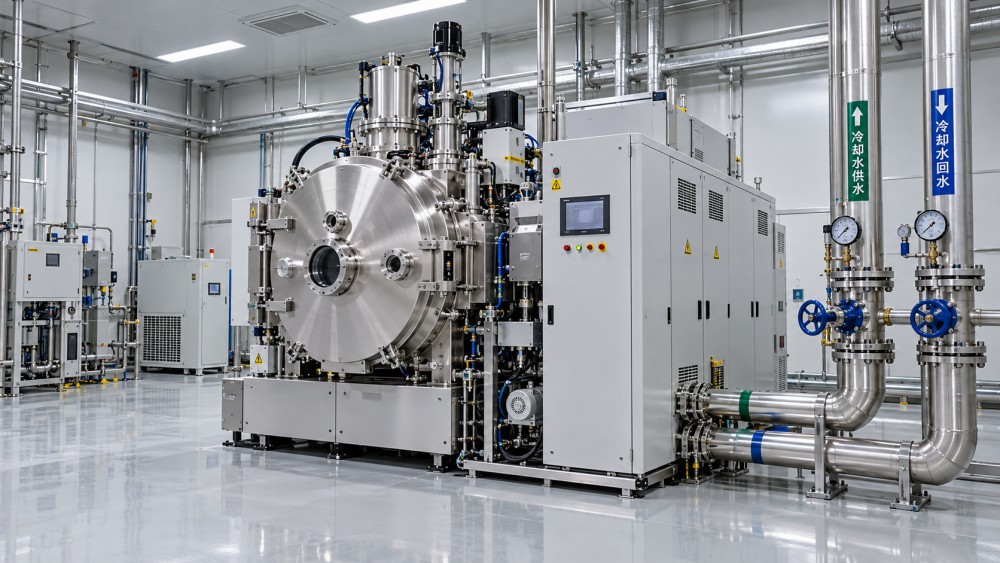
A shared facility supply can support a PVD tool when it delivers the required cooling capacity and water conditions at the tool connection during all operating modes.
The important distinction is between a shared source and an uncontrolled source. A central system may serve many tools while still providing stable, monitored water to each connection.
Ask the equipment manufacturer for the installation specifications for the exact tool configuration, including chamber count, power supplies, pumps, accessories, and any planned future additions.
Compare those requirements with measured conditions at the proposed installation point, not just the central plant’s nameplate capacity or a utility drawing prepared years earlier.
Verify available flow and supply pressure when neighboring equipment is operating. Also check return pressure, because the pressure difference across the tool determines whether water can circulate as intended.
Shared cooling is a reasonable starting assumption for a fab with sufficient capacity, compatible water quality, and documented utility stability. It is not an automatic approval.
When Does a PVD Tool Need a Dedicated Chiller or Cooling Loop?
A dedicated solution becomes more compelling when facility water cannot consistently meet the tool’s limits, or when the manufacturer requires cooling conditions the shared network cannot provide.
For example, a tool may require tighter inlet-temperature control than the plant system offers. A chiller or temperature-controlled loop may then help maintain the specified conditions.
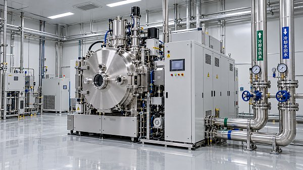
An isolated loop with a heat exchanger can separate the tool’s coolant from facility water. That arrangement may address water compatibility or contamination concerns without creating an independent heat sink.
A dedicated chiller can control the tool-side coolant, but many chillers still reject heat to facility water or building air. Their own utility requirements must be included in the design.
Consider dedicated equipment when pressure fluctuations, seasonal temperature changes, or competing loads threaten tool operation, and when correcting the shared system would be impractical or more expensive.
Isolation may also be justified where a tool contains sensitive materials, where coolant chemistry differs from the plant standard, or where an OEM specifies a closed loop.
Conversely, a separate chiller adds equipment, maintenance, controls, floor-space requirements, and potential failure points. It should solve a defined problem, not simply provide an appearance of independence.
Confirm that the proposed arrangement preserves warranty coverage and satisfies the tool supplier’s requirements. A technically plausible design is not a substitute for configuration-specific approval.
What Cooling Specifications Should the Facility Team Check?
The equipment utility matrix is the starting point. Request operating limits, preferred setpoints, maximum design conditions, connection details, alarm thresholds, and the basis for each stated value.
Heat load and operating profile
Heat load determines how much energy the cooling system must remove. It can vary with deposition power, process recipe, duty cycle, chamber operation, and auxiliary equipment.
Ask for both peak and normal operating loads, with the conditions behind each figure. A single maximum number is useful for design but insufficient for estimating typical energy use.
Identify which components are included in the stated load. A chamber specification may exclude vacuum pumps, power supplies, chillers, or other equipment that also needs cooling.
Flow, pressure, and temperature
Compare the required flow range and minimum differential pressure with conditions at the tool’s supply and return connections. Excessive pressure can also exceed equipment limits.
Check the permitted inlet-temperature range, stability requirements, and expected return temperature. Temperature control matters because cooling performance depends on both water flow and heat absorption.
Do not assume colder water is better. Water below the surrounding air’s dew point can cause condensation, while temperatures outside the specified range can affect equipment performance.
Review humidity, insulation, leak detection, and the OEM’s minimum coolant temperature together. The facility team should assess condensation risk under the actual installation environment.
Water quality and materials
Water requirements can include conductivity or resistivity, pH, particulate limits, hardness, and restrictions on dissolved oxygen or treatment chemicals. Obtain the limits for each cooling circuit.
Do not assume that high-purity deionized water is universally appropriate. Water chemistry must be compatible with the tool’s metals, seals, heat exchangers, and manufacturer-approved treatment program.
Incompatible water can contribute to corrosion, deposits, or fouling. These problems may reduce heat transfer or restrict flow before they produce an obvious equipment fault.
Confirm sampling locations, filtration responsibilities, cleaning intervals, and who maintains water quality. The plant standard and the tool specification must be compared parameter by parameter.
How Should You Estimate Cooling Capacity?
For a preliminary check, heat removal can be estimated from coolant flow and its temperature rise. For water, a useful approximation is shown below.
Heat load in kilowatts is approximately 0.0698 multiplied by flow in liters per minute and the temperature rise in degrees Celsius.
For example, 30 liters per minute with a 5°C temperature rise corresponds to roughly 10.5 kW of heat removal, assuming ordinary water properties and steady conditions.
This example illustrates the relationship; it is not a recommended PVD setting. Actual design must use the manufacturer’s permitted flow and temperature limits and relevant coolant properties.
Reverse the calculation only as a screening exercise. A calculated flow may not satisfy the tool’s minimum flow, pressure, component cooling, or temperature-stability requirements.
For a shared system, evaluate coincident demand across tools rather than adding only average loads. Include realistic operating scenarios, redundancy requirements, distribution losses, and future expansion.
The capacity study should also consider the central system’s ability to reject heat during the hottest expected conditions. Nominal chiller capacity may not be available at every operating point.
Use the facility’s design practices and supplier data to select any engineering margin. Avoid presenting a generic percentage as suitable for every tool and plant.
What Happens If Cooling Water Is Unstable?
Cooling instability can lead to alarms, power derating, interrupted runs, or equipment shutdown, depending on the tool’s interlocks and operating limits.
Temperature variation may also affect component temperatures and process repeatability. Whether it changes film properties or yield depends on the tool, recipe, control system, and degree of variation.
Low flow or inadequate pressure can reduce cooling effectiveness even when the supply temperature appears acceptable. Monitoring temperature alone may therefore miss an emerging problem.
Changes in water chemistry can cause deposits or corrosion over time. A system that passes installation checks may still need ongoing monitoring to remain within specification.
Ask the OEM what the tool does after a cooling interruption: whether it stops deposition, protects components automatically, requires manual recovery, or needs a qualification check before production.
For production planning, translate these failure modes into potential lost wafers, recovery time, maintenance effort, and qualification exposure. These costs depend on the process and facility operating model.
How Should Procurement Compare Cooling Options?
Issue the same operating assumptions to competing suppliers, including facility water conditions, ambient temperature, target uptime, planned recipes, and expected utilization.
Request a boundary diagram showing which supplier provides the tool, chiller, heat exchanger, pumps, filtration, controls, pipework, and connections to the facility.
Compare installed cost rather than equipment price alone. Include distribution modifications, electrical work, controls integration, floor space, commissioning, and any necessary upgrades to heat rejection.
Estimate operating costs using local electricity and water prices, expected load profiles, maintenance schedules, consumables, and service contracts. Record the assumptions behind every comparison.
Review spare parts and local service availability for the cooling system as well as the PVD tool. A critical cooling component can become a tool-availability constraint.
Clarify warranty boundaries and response responsibilities when an alarm involves both the tool and facility utilities. Undefined ownership can delay troubleshooting and acceptance.
Where redundancy is proposed, establish what it actually protects: a pump, a chiller, power supply, controls, or the entire heat-rejection path. Full independence requires more than duplicate equipment.
What Should Be Verified Before Installation and Acceptance?
Begin with a joint review involving facilities, process engineering, environmental health and safety, procurement, the tool supplier, and the cooling-system provider where applicable.
Document the approved utility matrix and connection locations. Resolve differences between preliminary sales information, the final configuration, and the installation manual before construction begins.
Measure supply temperature, flow, pressure, differential pressure, and water quality at the proposed connection. Test under representative plant loading and relevant seasonal conditions where practical.
Confirm whether isolation valves, strainers, meters, leak detection, backflow protection, and drain provisions are required by the design, local rules, or supplier instructions.
Before connecting the tool, flush and commission pipework according to the approved procedure. Verify that cleaning chemicals and any residual contaminants are compatible with the equipment.
During acceptance, demonstrate that cooling conditions remain within specified limits during agreed tool operating modes. Record readings, alarm behavior, and any deviations requiring corrective action.
Agree on monitoring points and ownership after handover. Trend data can help teams distinguish a facility utility problem from a tool-side restriction or component failure.
Questions to Ask the PVD Supplier
Before placing an order, request written answers tied to the proposed configuration. The following questions make cooling requirements easier to compare across quotations.
- What are the minimum, normal, and maximum cooling flows, inlet pressures, and required pressure differentials for each circuit?
- What inlet-temperature range and stability are required, and what are the peak and typical heat loads under defined operating conditions?
- Which water-quality limits and approved treatment methods apply, and are different requirements specified for separate circuits?
- Can the tool connect directly to the proposed shared supply, or is an isolated loop, heat exchanger, or chiller required?
- What happens during loss of flow or temperature excursions, and what recovery or process requalification may be necessary?
- Who supplies, installs, commissions, maintains, and supports each cooling component, and what evidence is required for acceptance?
Request updated answers whenever the configuration changes. Additional chambers, pumps, or higher-power options can change utility demand and invalidate an earlier facilities assessment.
Conclusion
A PVD tool does not automatically need a dedicated cooling water supply. A shared facility system can be suitable when it meets the exact tool’s documented requirements consistently.
Choose a dedicated chiller or isolated loop when a specific control, compatibility, reliability, or manufacturer requirement justifies it, and account for the complete heat-rejection path.
The practical decision is made at the tool connection: verify capacity, flow, pressure, temperature, water quality, and operating stability, then document acceptance and ongoing ownership.
Questions about market trends? Contact Market Scope Live for deeper business insights.
We respect your privacy. Your information is strictly confidential.
We respect your privacy. Your information is strictly confidential.
Related News
 Wafer Fab EquipmentHow to size semiconductor manufacturing equipment for wafer fabsSize semiconductor manufacturing equipment for wafer fabs with confidence. Learn to model capacity, assess bottlenecks, and make smarter procurement decisions.MORE+
 Wafer Fab EquipmentWhen should semiconductor manufacturing equipment maintenance be scheduled?Semiconductor manufacturing equipment maintenance should follow approved time, usage, and condition limits. Learn how to schedule service and protect production.MORE+
 Wafer Fab EquipmentWhen should chemical vapor deposition equipment be cleaned?Chemical Vapor Deposition Equipment cleaning depends on buildup, defect trends and validated limits. Learn when to act to protect wafer quality and uptime.MORE+
 Wafer Fab EquipmentHow residual gas analyzers help detect vacuum chamber leaksResidual Gas Analyzers help detect vacuum chamber leaks. Explore gas signatures, tracer testing, and practical steps to pinpoint problems with confidence.MORE+
 Wafer Fab EquipmentHow to Test Material Handling Recovery After a Power OutageHow can I test material handling recovery after a power outage? Explore a practical guide to verifying carrier locations, safe transfers, and system readiness.MORE+
 Wafer Fab EquipmentWhat to Do When a Wafer Handling Robot Drops a WaferWhat should I do if a wafer handling robot drops a wafer? Learn how to contain risks, protect affected lots, investigate the cause, and safely restart production.MORE+
 Wafer Fab EquipmentDoes a PVD Tool Need a Dedicated Cooling Water Supply?Does a PVD tool need a dedicated cooling water supply? Discover when shared cooling works, when a chiller is needed, and what to check before installation.MORE+
 Wafer Fab EquipmentRapid thermal processing or batch furnaces for wafer annealing?Semiconductor Thermal Processing Equipment: Compare RTP and batch furnaces for wafer annealing to find the right fit for your process, throughput and yield goals.MORE+
 Wafer Fab EquipmentPreventing moisture contamination in semiconductor gas delivery systemsSemiconductor Gas Delivery Systems need effective moisture control. Discover practical design, monitoring, and maintenance strategies to protect gas purity.MORE+