How residual gas analyzers help detect vacuum chamber leaks
Author
Date Published
Reading Time
A vacuum chamber that pumps down slowly, shows an elevated base pressure, or produces inconsistent process results may have a leak. Residual Gas Analyzers (RGAs) help operators investigate by showing which gas species are present and how their signals change. A combination of rising nitrogen and oxygen signals, for example, can point toward air entering the vacuum system.
An RGA reading alone rarely identifies the location or size of a leak. Similar signals can come from trapped gas, desorption from chamber surfaces, process residues, or the sampling system itself. The most useful approach is to compare the spectrum with a known baseline, test how it responds to controlled changes, and use a suitable tracer-gas leak test when the evidence points to an external leak.
What an RGA can reveal about a suspected leak
An RGA measures signals associated with gas ions at different mass-to-charge ratios, commonly displayed as mass peaks. In a vacuum chamber, those peaks can help an operator distinguish an air-like gas load from water vapor, hydrocarbons, process gases, or a deliberate tracer gas. The trend is often more informative than any single spectrum: a reading taken after maintenance, for instance, becomes easier to interpret when it can be compared with a spectrum from the same chamber under similar conditions.
For an air leak, operators often examine the peaks near mass-to-charge ratios 28 and 32, commonly associated with nitrogen and oxygen, along with the peak near 40, associated with argon. Their combined behavior can support an air-ingress diagnosis. A simultaneous rise after a flange is disturbed, followed by a response during a targeted tracer test, is more persuasive than a high mass-28 signal on its own.
Peak identification requires care. Mass 28 can include carbon monoxide as well as nitrogen; mass 32 may have contributions from other species; and fragmentation in the ion source can produce peaks that overlap with those of other gases. Relative peak heights also depend on instrument sensitivity and operating conditions, so they should not be treated as a direct, universal air-composition ratio. Use the instrument’s documented cracking patterns and sensitivity information when the distinction matters.
Partial-pressure trends also depend on the vacuum system. Pumping speeds differ by gas species, and a spectrum taken close to a gas inlet or through a restricted sampling line may not represent the entire chamber. Record the measurement location and valve configuration before comparing readings.
Separate a leak from gas already inside the system
After a chamber has been opened, water and other gases can remain on internal surfaces. They may be released during pumpdown and produce an elevated residual-gas signal without any continuing path to atmosphere. A trapped volume behind a fitting or component can similarly release gas over time; this is often called a virtual leak.
Start with the chamber’s recent history. Was it vented, cleaned, heated, serviced, or exposed to a new process chemistry? Has a seal, feedthrough, valve, or sampling connection been disturbed? A chamber immediately after maintenance may need a different comparison point from one that has completed its normal conditioning cycle.
The following observations can guide the next test, although none is conclusive by itself:
- Air-like peaks persist or increase: Compare nitrogen, oxygen, and argon signals over time and investigate disturbed joints or components. A real air leak remains a possibility even if one expected peak is weak or masked.
- Water dominates and decreases during pumpdown: Surface moisture or recent exposure to air may be contributing. Follow the approved conditioning procedure before deciding that the chamber has a leak.
- Pressure or gas signals fall slowly after isolation: Outgassing, trapped volumes, a leak, or more than one of these may be involved. A pressure-rise test alone does not reliably separate them.
- A process-related peak changes: Check gas delivery, valve leakage, residues, and the prior process history. An unexpected gas is not necessarily entering from outside the tool.
Isolation tests can narrow the search when the equipment procedure permits them. Comparing readings with a branch, load lock, gas line, or pump connection isolated may show which section contributes to the gas load. Valve positions and pump configuration must be documented: changing either can alter pressure and peak ratios without eliminating the underlying source.
Use a tracer response to narrow the location
Once an air leak is plausible, a tracer gas can help locate its entry point. Helium is commonly used because its signal can be monitored at mass 4 and its concentration around the test area can be deliberately changed. Depending on the system, the measurement may use the RGA, a dedicated helium leak detector, or both.
A controlled external spray test applies a small amount of tracer to one accessible suspect area at a time while the chamber is under vacuum. If tracer enters through a leak and reaches the analyzer, the corresponding signal rises after a delay. That response links the suspect area to the signal more directly than a general air signature does, but it does not automatically identify the exact defect within that area.
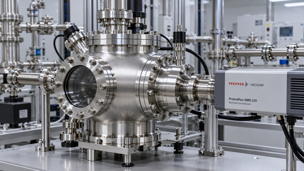
A practical sequence is:
- Establish a stable background signal at the tracer mass with the chamber and analyzer in the approved configuration.
- Apply tracer briefly to one joint, seal, weld, feedthrough, or other accessible suspect point. Keep the application localized.
- Watch for a response and allow enough time for gas to travel through the system. The delay depends on the leak location, conductance, pumping arrangement, and analyzer position.
- Stop applying tracer, allow the signal to recover, and repeat at the same point. Then test adjacent points separately.
- Record the location, valve states, background, response, and timing. Confirm a repair with a repeat test under comparable conditions.
A broad spray over several connections can make the first response difficult to attribute. Tracer can also accumulate around the equipment and enter through a leak elsewhere, producing a misleading indication. Ventilate the surrounding area as required by site procedures and wait for the background to return before moving to another location.
A missing response does not prove that a joint is sound. The tracer may not reach the leak opening, the leak may be shielded, the signal may arrive later than expected, or the test configuration may pump the tracer away before enough reaches the analyzer. Some failures also appear only under particular temperature, mechanical, or valve conditions. Reconsider the test setup if other evidence continues to indicate leakage.
Know when the RGA is not enough
An RGA is especially useful when operators need to understand what is entering or being released into the vacuum space. A calibrated leak detector is generally the more appropriate tool when an acceptance procedure requires a quantified tracer-gas leak rate. An RGA tracer peak depends on factors such as analyzer sensitivity, pumping speed, gas transport, and background; it should not be converted into a leak-rate claim without a validated method and suitable calibration.
Likewise, a measured helium leak rate cannot be assumed to equal the operating air leak rate under every condition. The relationship depends on the leak path and pressure conditions. For acceptance, use the test gas, configuration, calibration, and limit specified for the equipment or site procedure.
The analyzer must also be operated within its permitted pressure range. A sudden vent, process-gas exposure, or incorrect valve sequence can damage the instrument or contaminate the measurement path. Check interlocks and the manufacturer’s operating instructions before connecting or exposing it to the chamber. Where hazardous process gases or residues may be present, follow the facility’s isolation, purge, exhaust, and maintenance controls; tracer testing does not replace those precautions.
After a suspected leak has been repaired, the useful evidence is a repeatable result: the tracer response at the repaired location is absent or within the applicable acceptance limit, the chamber reaches its expected vacuum behavior, and the residual-gas spectrum returns toward an appropriate baseline. Keep those readings with the maintenance record so that the next investigation starts with a comparison that matches the tool’s actual operating conditions.
Questions about market trends? Contact Market Scope Live for deeper business insights.
We respect your privacy. Your information is strictly confidential.
We respect your privacy. Your information is strictly confidential.
Related News
 Wafer Fab EquipmentHow to size semiconductor manufacturing equipment for wafer fabsSize semiconductor manufacturing equipment for wafer fabs with confidence. Learn to model capacity, assess bottlenecks, and make smarter procurement decisions.MORE+
 Wafer Fab EquipmentWhen should semiconductor manufacturing equipment maintenance be scheduled?Semiconductor manufacturing equipment maintenance should follow approved time, usage, and condition limits. Learn how to schedule service and protect production.MORE+
 Wafer Fab EquipmentWhen should chemical vapor deposition equipment be cleaned?Chemical Vapor Deposition Equipment cleaning depends on buildup, defect trends and validated limits. Learn when to act to protect wafer quality and uptime.MORE+
 Wafer Fab EquipmentHow residual gas analyzers help detect vacuum chamber leaksResidual Gas Analyzers help detect vacuum chamber leaks. Explore gas signatures, tracer testing, and practical steps to pinpoint problems with confidence.MORE+
 Wafer Fab EquipmentHow to Test Material Handling Recovery After a Power OutageHow can I test material handling recovery after a power outage? Explore a practical guide to verifying carrier locations, safe transfers, and system readiness.MORE+
 Wafer Fab EquipmentWhat to Do When a Wafer Handling Robot Drops a WaferWhat should I do if a wafer handling robot drops a wafer? Learn how to contain risks, protect affected lots, investigate the cause, and safely restart production.MORE+
 Wafer Fab EquipmentDoes a PVD Tool Need a Dedicated Cooling Water Supply?Does a PVD tool need a dedicated cooling water supply? Discover when shared cooling works, when a chiller is needed, and what to check before installation.MORE+
 Wafer Fab EquipmentRapid thermal processing or batch furnaces for wafer annealing?Semiconductor Thermal Processing Equipment: Compare RTP and batch furnaces for wafer annealing to find the right fit for your process, throughput and yield goals.MORE+
 Wafer Fab EquipmentPreventing moisture contamination in semiconductor gas delivery systemsSemiconductor Gas Delivery Systems need effective moisture control. Discover practical design, monitoring, and maintenance strategies to protect gas purity.MORE+